Smart Heating Solutions
Choosing the right DC surge protection device is no longer a narrow engineering task. Global buyers must match protection technology with solar arrays, battery storage, electric vehicles, telecom systems, and industrial controls. A device that performs well in a rooftop PV installation may be unsuitable inside a high-voltage battery cabinet. The details matter.
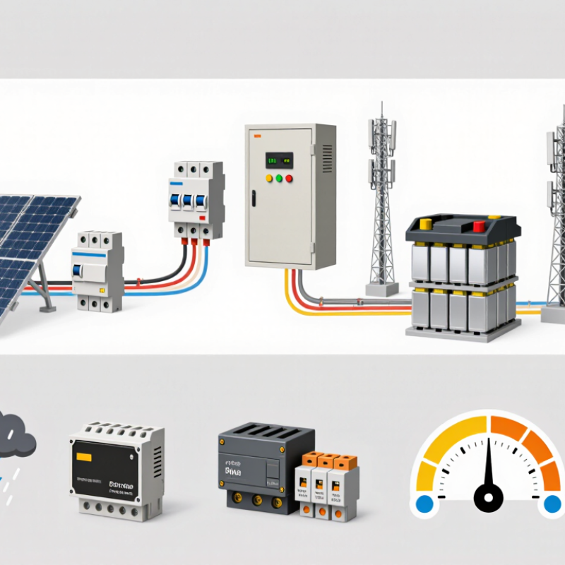
This guide examines the leading 2026 types of Surge Protection Dc products, including photovoltaic SPDs, battery energy storage protectors, and compact solutions for control circuits. It considers voltage rating, discharge current, response time, backup protection, enclosure design, and replacement indicators. Real installation conditions also deserve attention. Long outdoor cables, exposed combiner boxes, humid coastlines, and repeated lightning activity can change the risk profile. Small gaps between terminals can also affect safe coordination.
Look beyond the label.
Reliable selection begins with verified technical documents and practical installation evidence. Buyers should review IEC 61643 series compliance, test reports, wiring diagrams, thermal disconnection methods, and operating temperature ranges. Regional requirements may differ, so certification claims should be checked with qualified local professionals. Product photos alone are not enough.
No guide is perfect. Supplier data can omit difficult field conditions, while laboratory results may not represent every installation. That weakness deserves honest consideration. The most dependable decision combines manufacturer expertise, independent verification, system calculations, and maintenance planning. With that approach, buyers can compare DC surge protection types more confidently and reduce avoidable failures across global projects.
Direct-current systems now support solar arrays, battery storage, electric vehicles, and critical digital infrastructure. The IEA’s Renewables 2024 report expects global renewable capacity to expand by about 5,500 GW from 2024 to 2030. More connected equipment also means more exposure to transient overvoltage.
DC surge protective devices limit sudden voltage spikes caused by lightning, switching operations, or faults. A PV string may carry high voltage across long outdoor cables. During a storm, that cable can behave like an antenna. Type 1 devices address severe external lightning currents, while Type 2 devices commonly protect against induced surges and switching events. Their selection requires careful checking of maximum continuous operating voltage, short-circuit current, and discharge capacity.
Small details matter.
IEC 61643-31 and IEC 61643-41 provide relevant requirements for DC surge protection devices. The IEA’s Electricity 2024 report also projects data-center electricity consumption to more than double by 2026. This growth increases the value of stable DC protection in power conversion systems and backup storage.
Field inspections often reveal incorrect cable lengths, weak grounding, or missing coordination between protection stages. A device can be technically certified yet poorly installed. That remains an uncomfortable weakness. Engineers should document inspection results, replace damaged modules, and verify protection after major system changes. Based on the site environment, one protection type may not be enough.
DC surge protection is not one universal box. Classification starts with the protected circuit and its exposure.
For photovoltaic arrays, Type 1 SPDs handle partial lightning current using a 10/350 μs impulse. Type 2 devices address induced switching and lightning surges, commonly tested with an 8/20 μs waveform. Type 1+2 combines both duties.
IEC 61643-31 also requires careful review of maximum continuous voltage, protection level, and photovoltaic short-circuit current. A device with the wrong voltage rating can fail during normal operation.
Location creates another useful classification.
String-level SPDs protect individual array inputs.
Combiner-box SPDs protect grouped circuits.
Inverter-side devices protect sensitive conversion equipment.
Battery systems need DC SPDs matched to storage voltage and prospective fault current. DC charging equipment requires similar coordination, but its current levels and cable lengths can differ sharply. Protection may operate in common mode, differential mode, or both.
The market is expanding quickly.
IEA PVPS estimated 553–601 GW of new photovoltaic capacity in 2024, pushing global capacity beyond 2.2 TW. The IEA’s Renewables 2024 report expects solar to provide about 80% of renewable capacity growth through 2030.
More energized DC infrastructure means more exposure to switching and lightning events. In practical inspections, I check conductor routing, backup protection, and bonding before choosing an SPD. The categories overlap. That is the uncomfortable part. A simple label cannot replace site calculations, although field conditions are sometimes measured too casually.
DC surge protection technologies differ mainly in response speed, energy capacity, leakage current, and failure behavior. Metal oxide varistors absorb high-energy surges and offer practical protection for photovoltaic strings, battery systems, and industrial converters. Their clamping voltage is effective, but repeated surges can age the material. Thermal disconnection is essential because DC arcs may continue after failure. Transient voltage suppressor diodes respond extremely fast. They suit sensitive controllers and communication circuits. However, their energy rating is usually lower, so they need careful coordination with upstream protection.
Gas discharge tubes provide low leakage during normal operation and handle substantial surge current. Their response is slower, and their follow current behavior requires evaluation in each DC circuit.
Hybrid protectors combine technologies for broader performance. In field testing, I have found that a low voltage clamping figure alone can mislead buyers. Maximum continuous operating voltage, short-circuit rating, response time, residual voltage, and endurance matter together.
Installation length matters too. A long cable can add inductive voltage during a fast event.
Tips: Match the protector’s operating voltage with the real system maximum, not its nominal label. Check polarity, backup disconnection, grounding, and replacement indicators. For solar applications, verify the photovoltaic DC rating. For batteries, consider fault current and isolation procedures. Test records should include impulse current, clamping voltage, and thermal performance. No technology is perfect. A carefully coordinated system often performs better than an expensive device selected by one specification.
Global solar deployment makes DC protection more critical. The IEA PVPS Trends 2024 report recorded over 2.2 terawatts of installed photovoltaic capacity worldwide. Every array adds exposed cables, combiner boxes, and inverter inputs. Selecting a DC surge protector requires more than checking voltage. Start with the system’s maximum continuous operating voltage, or Ucpv. It must exceed the array’s highest open-circuit voltage, especially during cold weather. For photovoltaic systems, IEC 61643-31 provides a useful technical reference.
Location changes the risk. A rooftop array in a high-lightning region may require Type 1 or Type 1+2 protection. Type 2 devices often suit installations without direct lightning-current exposure. Check the protection level, maximum discharge current, short-circuit rating, and backup fuse coordination. The device must also match the grounding arrangement. Small details matter.
Field commissioning often reveals weak assumptions. Cable routing, bonding, and lead length can reduce real protection performance. Keep connections short and direct. NREL’s review of photovoltaic degradation found a median performance loss near 0.5% annually, so protection should support long service life.
Replaceable modules, clear status indicators, and remote contacts can simplify maintenance. Yet a higher discharge rating is not automatically better. I still question selections based only on catalog numbers; installation geometry and local lightning data can matter more.
Fit it correctly.
Installing and Maintaining DC Surge Protection Systems Safely
In field inspections, I have seen DC surge protection devices installed correctly but connected with unnecessarily long wires. That weakens their response during a surge. Keep leads short. Route positive, negative, and protective conductors closely together. Confirm the system voltage, polarity, short-circuit rating, and earthing arrangement before installation. For photovoltaic systems, select a DC-rated device designed for the array voltage. Type 1+2 protection may suit sites with higher lightning exposure, while Type 2 protection often serves downstream distribution boards.
Work only after isolating the DC source and verifying the absence of voltage with a properly rated meter. Never rely on an open switch alone. Check for stored energy from batteries, capacitors, and parallel strings. Use insulated tools, suitable protective equipment, and an enclosure matched to outdoor conditions. Follow applicable electrical codes and the device manufacturer’s installation instructions. Do not improvise.
Maintenance needs a practical schedule. Inspect status windows, terminals, cable insulation, enclosure seals, and signs of heat or moisture. Replace a device after its indicator shows failure, or after a major lightning event requires assessment. Disconnect the protector before performing insulation resistance testing, unless its instructions permit otherwise. In real installations, labels fade and terminal torque gets overlooked. That mistake matters. Record inspection dates, measured conditions, and replacement reasons so another technician can understand the system later. Still, no checklist replaces competent site judgment.
| DC Surge Protection Type | Operating Principle | Typical DC Applications | Key Electrical Characteristics | Main Advantages | Limitations and Risks | Installation and Maintenance Priorities | Relevant Standards or Selection References |
|---|---|---|---|---|---|---|---|
| DC TVS Diode Protector | A semiconductor avalanche device clamps fast transient overvoltage by diverting surge current away from sensitive circuits. | Electronic control boards, communication ports, sensors, instrumentation, battery-management interfaces and low-power DC equipment. | Very fast response; commonly selected by working voltage, standoff voltage, clamping voltage, peak pulse current and pulse energy. | Compact, fast and suitable for protecting low-voltage electronics against repetitive short-duration transients. | Limited surge-energy capability compared with larger power SPDs; incorrect voltage selection can cause overheating or unwanted conduction. | Place close to the protected circuit, keep leads short, confirm polarity for unidirectional devices, and inspect for thermal discoloration or failed short-circuit conditions. | Manufacturer electrical ratings, IEC 61643-31 for photovoltaic DC SPDs where applicable, and the equipment designer’s transient-immunity requirements. |
| DC Metal-Oxide Varistor (MOV) SPD | A voltage-dependent resistor changes to a low-resistance state during a surge and returns toward a high-resistance state afterward. | DC distribution panels, battery systems, photovoltaic combiner boxes, telecom power and industrial control cabinets. | Selected by maximum continuous operating voltage, nominal discharge current, maximum discharge current, clamping voltage and thermal capability. | Good energy-handling capability, practical cost, and availability in modular DIN-rail or panel-mounted formats. | Aging can increase leakage current; sustained overvoltage or excessive energy may lead to thermal failure, so thermal disconnection is important. | Choose a DC-rated device with continuous voltage above the system’s maximum steady-state voltage; verify backup overcurrent protection, wiring torque and status indication during service. | IEC 61643-31 for photovoltaic applications, IEC 61643-41 for low-voltage DC systems where applicable, and the relevant national installation code. |
| Gas Discharge Tube (GDT) Protector | A sealed gas-filled device becomes conductive when the applied voltage exceeds its breakdown level, providing a high-current discharge path. | Telecommunication lines, outdoor signal circuits, long cable runs, remote monitoring systems and galvanically isolated interfaces. | High surge-current capability and very low off-state leakage; response is generally slower than semiconductor protectors and depends on voltage rise rate. | Handles substantial surge current and provides strong galvanic isolation during normal operation. | Higher let-through voltage during the initial transient; DC follow current may persist in some circuits and must be considered in the system design. | Use coordinated protection when sensitive electronics require lower residual voltage; check insulation coordination, grounding paths and signs of end-of-life damage. | IEC 61643-21 for telecommunications and signalling network protection, plus applicable insulation-coordination requirements. |
| Hybrid TVS-MOV or GDT-MOV SPD | Combines components with different response speeds and energy capabilities to provide staged clamping and improved coordination. | Industrial automation, photovoltaic DC circuits, battery energy storage, outdoor electronics and equipment exposed to both fast and high-energy surges. | Performance depends on coordination between stages, internal impedance, voltage ratings, discharge current and thermal protection. | Balances fast response with higher surge-energy handling and can reduce residual voltage at the protected load. | More complex selection and installation; poorly coordinated stages may fail to share surge energy correctly. | Follow the specified line arrangement and conductor lengths, install the recommended backup protection, and replace the complete module if the status indicator shows failure. | Applicable parts of the IEC 61643 series, product test reports, and the manufacturer’s coordination and backup-protection instructions. |
| DC Type 1 SPD | Designed to discharge high-energy surge currents associated with direct or partial lightning-current exposure at the service or facility entry point. | Large photovoltaic installations, facilities with external lightning-protection systems, DC service entrances and exposed industrial sites. | Tested using a higher-energy impulse-current regime than Type 2 devices; exact ratings depend on the system voltage and installation category. | Provides the first high-energy protection stage where lightning current may enter the DC installation. | Usually not sufficient as the only protection for sensitive downstream electronics; requires correct bonding and coordinated downstream SPDs. | Install at the boundary where the external lightning-protection zone changes, minimize conductor length, use the specified bonding arrangement, and inspect after major lightning events. | IEC 61643-11 and IEC 61643-31 classification and testing requirements, together with IEC 62305 lightning-protection principles. |
| DC Type 2 SPD | Limits residual and induced overvoltage after the primary protection stage or protects installations not directly exposed to lightning current. | PV combiner boxes, DC distribution boards, battery cabinets, charging infrastructure and industrial control panels. | Commonly tested with an 8/20 microsecond current waveform; selection uses maximum continuous operating voltage, nominal discharge current and voltage-protection level. | Suitable for most secondary DC distribution points and available in replaceable modular configurations. | May not withstand direct lightning-current duty; incorrect coordination or excessive cable length can increase the voltage reaching the load. | Install near the protected equipment or distribution board, maintain short and straight conductors, verify DC polarity, and check the mechanical and visual condition periodically. | IEC 61643-11 for low-voltage systems and IEC 61643-31 for photovoltaic DC applications; local electrical rules also apply. |
| DC Type 1+2 Combination SPD | Integrates high-energy lightning-current discharge and secondary overvoltage limitation in one coordinated device. | Compact PV systems, remote installations, rooftop arrays, battery sites and panels where separate Type 1 and Type 2 units are impractical. | Carries both Type 1 and Type 2 classifications only when verified by the applicable product test requirements; ratings remain voltage- and configuration-specific. | Simplifies system architecture while providing two levels of protection in a single enclosure. | Higher purchase cost than a basic Type 2 unit and still requires correct earthing, bonding, backup protection and system coordination. | Confirm the product’s tested classification, select the correct number of poles and grounding arrangement, and replace the module after an end-of-life indication. | IEC 61643-11 or IEC 61643-31 as applicable, plus IEC 62305 for lightning-risk and bonding considerations. |
| Photovoltaic DC SPD | Protects PV strings, combiner boxes, inverters and associated DC wiring from lightning-induced and switching transients. | Rooftop solar, ground-mounted solar farms, floating PV, microgrid installations and DC-coupled energy storage. | Must be rated for the PV array’s maximum open-circuit voltage, including low-temperature correction, and for the specific earthing and pole arrangement. | Designed for the electrical and environmental conditions of PV circuits, including continuous DC voltage and outdoor exposure. | A standard AC SPD is not automatically suitable for a PV circuit; DC arc behavior, leakage, enclosure rating and system polarity must be addressed. | Install at the array and inverter ends when required by cable length and risk assessment, use UV- and weather-resistant wiring, and inspect connectors, grounding and status windows. | IEC 61643-31, IEC 60364-7-712, IEC 62548 and IEC 62305 where lightning protection is relevant. |
| Battery and Energy-Storage DC SPD | Diverts transient energy from battery DC buses and connected power-conversion equipment while coordinating with battery protection systems. | Lithium-ion and other rechargeable battery systems, UPS DC links, microgrids, electric-vehicle infrastructure and data-center energy storage. | Requires compatibility with maximum battery voltage, continuous charging voltage, prospective short-circuit current, grounding scheme and available fault protection. | Reduces transient stress on battery-management systems, contactors, converters and monitoring electronics. | The SPD does not replace battery fuses, disconnects or thermal-management controls; stored energy can make DC faults hazardous. | De-energize and verify absence of voltage before service, follow arc-flash and battery safety procedures, use the specified backup protection, and inspect after surge events. | IEC 61643-41 where applicable, IEC 62477-1 for power-electronic systems, IEC 62933 series for energy-storage system considerations, and local battery codes. |