Smart Heating Solutions
Choosing Aluminum Solar Rails in 2026 means balancing structural performance, installation speed, and long-term exposure—not simply comparing price per meter. IEA PVPS’s Trends in Photovoltaic Applications 2024 report estimated that global solar capacity reached about 1.6 terawatts in 2023, after roughly 447 gigawatts of additions. That expanding installed base makes small design decisions consequential. A rail must fit the module clamp zone, span the planned support points, and work with the roof or ground-mount system. It also needs credible load calculations and clear material specifications. Details matter.
Sarah Kurtz, a photovoltaic reliability researcher associated with the U.S. National Renewable Energy Laboratory, is a relevant expert on long-term PV performance. Her research supports a practical selection principle: evaluate reliability over the system’s service life, not just at installation. This is a paraphrase of her broader work, not a verified verbatim quotation about solar rails. For buyers, that means checking alloy and temper, wall thickness, connection design, finish, and documented wind and snow-load assumptions. Ask for test reports and installation guidance, then compare them against the project’s actual conditions. A neat extrusion is not proof of a sound system. Nor does the lightest rail automatically deliver the best value. This guide examines the trade-offs, questions suppliers should answer, and warning signs worth revisiting before purchase. The goal is a rail choice that installers can handle confidently and that owners can assess with evidence, not assumptions.
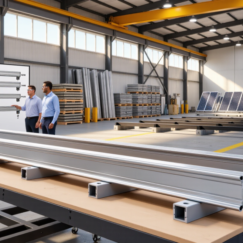
In 2026, choosing aluminum solar rails should begin with clear project requirements, not a product catalog. Record panel dimensions, array spacing, roof type, tilt angle, and mounting zones. Measure the roof twice, especially around vents and uneven surfaces. Small errors can create expensive alignment problems later. Check local wind, snow, seismic, and fire requirements before selecting rail size. A qualified installer or structural engineer should verify the load path from the panels to the building structure. Coastal projects also need stronger corrosion resistance and compatible fasteners.
Tips: Make a simple site sheet. Note roof age, material, drainage paths, and shaded areas. Keep spare rail length in the estimate. It is often overlooked. Confirm whether the system needs shared clamps, grounding hardware, or expansion gaps. Ask for load tables, installation instructions, and material details from the supplier. Clear documents make technical decisions easier to audit.
Think about installation conditions as well as final capacity. Long rails may reduce joints, but they can be difficult to carry across a narrow roof. Shorter sections may fit better, yet they increase connection points. Aluminum expands with temperature changes, so thermal movement deserves attention in large arrays. I would also reserve space for future panels only when the roof structure and electrical design allow it. Sometimes the lowest initial cost creates more labor, noise, and waste on site. Recheck the plan before ordering.
How to Choose Aluminum Solar Rails in 2026
Rail profiles should match the panel layout, span, and local weather loads. A light, narrow rail may suit short spans with moderate wind. Heavier box-shaped profiles provide better stiffness across longer gaps. Open channels can simplify bolt placement, but they may twist more under uneven loading. Check the manufacturer’s deflection limits, not only the rail’s appearance.
Alloy choice matters. 6000-series aluminum, especially heat-treated grades such as 6063-T5 or 6061-T6, offers a useful balance of strength, weight, and corrosion resistance. T6 is usually stronger, while T5 can be easier to extrude and more economical. Load ratings must include snow, wind uplift, rail span, fastener spacing, and roof attachment strength. A rail rated for 2.0 kN should not be treated as universally safe. Its rating depends on the test setup.
Tips: Measure actual support spacing before selecting a profile. Keep the rail line straight. Use compatible stainless fasteners and isolate dissimilar metals where required. Inspect cut ends for burrs and damage. I once focused too much on rail strength and overlooked weak roof attachments. That mistake changed my checking process. Real projects are rarely perfect. Recheck calculations when panel dimensions, edge distances, or weather conditions change.
| Rail profile | Typical section characteristics | Common alloy options | Stiffness and weight considerations | Load-rating considerations | Typical selection use |
|---|---|---|---|---|---|
| Open C-channel | Open-sided section with a mounting channel or lip; profile dimensions and wall thickness vary by rail design. | Often 6063-T5 or 6063-T6 extruded aluminum. | Usually lighter and easier to handle than a deeper closed section of comparable length. Its open shape can be more sensitive to twisting, depending on geometry and restraint. | No universal capacity applies. Check the rail’s published span tables for downward pressure and wind uplift at the proposed support spacing. | Projects prioritizing low rail weight and straightforward module attachment, where the project-specific span table confirms adequate capacity. |
| Box or closed-section rail | Hollow or partially enclosed profile intended to provide greater torsional resistance than a comparable open section. | Commonly 6063-T5, 6063-T6, or other specified structural extrusion alloys. | A closed section can resist twisting effectively, but actual stiffness depends on section depth, wall thickness, and shape—not the profile label alone. | Use the exact profile’s tested or engineered load tables. Confirm support spacing, cantilever limits, splice locations, and attachment details. | Layouts where resistance to rail rotation or a stiffer section is beneficial, subject to engineering verification. |
| Deep or heavy-duty channel | Deeper and/or thicker section than a lighter channel; no single industry-wide dimension defines this category. | May use 6063-T6 or a higher-strength extrusion alloy such as 6005A-T5, as specified for the product. | Greater section depth can increase bending stiffness, while added material can increase weight. Compare section properties and mass per unit length. | Do not infer capacity from depth or alloy alone. Verify allowable spans and design loads for the complete rail-and-attachment assembly. | Higher-demand layouts or longer spans when the engineered system data supports the required loads. |
| Rail with a splice connection | Two or more rail lengths joined with an internal or external splice; joint design and location vary. | Rail and splice alloys may differ; follow the specified compatible components and installation instructions. | Overall rail behavior depends on splice fit, fasteners, and whether the joint is designed to transfer bending. A splice should not automatically be treated as a continuous rail. | Check whether the load table permits a splice at the proposed location and whether the joint is included in the tested or calculated configuration. | Long rail runs where transport, handling, or roof layout requires multiple rail lengths. |
| Alloy and temper | Indicative minimum yield strength | Practical comparison | What to verify |
|---|---|---|---|
| 6063-T5 | Approximately 110 MPa for commonly specified extrusion product ranges. | Widely used for architectural and mounting extrusions; often selected where formability and surface finish are important. | Confirm the governing material standard, product thickness, and certified properties for the actual rail. |
| 6063-T6 | Approximately 170 MPa for commonly specified extrusion product ranges. | Higher strength than 6063-T5 in typical specifications; rail capacity still depends on the section geometry and connections. | Verify the temper and material properties specified for the supplied extrusion, along with the rail system’s structural data. |
| 6005A-T5 | Approximately 215 MPa for commonly specified extrusion product ranges. | A higher-strength extrusion alloy option used in some structural applications; a stronger alloy does not by itself establish a rail’s allowable load. | Check applicable thickness-dependent material requirements, corrosion compatibility, and system-level design values. |
Load-rating note: Solar-rail load capacity is not a universal value for a profile or alloy. It depends on the exact section, rail span, support and splice locations, fasteners, module arrangement, roof attachment, and site-specific wind, snow, and seismic design loads. Compare manufacturer or engineer-provided tables using the same design basis, units, and safety factors; verify both downward loading and uplift.
Material note: Yield-strength figures are indicative minimum values commonly specified for extruded products and can vary with the governing standard, product form, and thickness. Use certified properties for the actual material supplied.
Choosing an aluminum solar rail starts with a precise compatibility check. A rail may look suitable, yet its slot width, height, or alloy strength can differ significantly. Confirm the panel frame thickness, approved clamp zones, and maximum overhang. Never rely on visual matching alone.
The IEA PVPS Trends 2024 report recorded about 456 GW of new photovoltaic capacity worldwide in 2023. This rapid expansion increases the importance of repeatable installation checks. During field inspections, installers often discover mismatched mid-clamps or bonding clips after rails are already cut. That mistake wastes time and may weaken electrical continuity. Check the rail’s load tables against local wind and snow conditions. Also verify bolt sizes, clamp engagement depth, and grounding compatibility. NREL reliability research consistently highlights mechanical stress, moisture, and installation quality as important factors in long-term module performance.
Before choosing aluminum solar rails, inspect the actual roof, not only the drawings. Record roof pitch, rafter spacing, membrane condition, drainage paths, and nearby trees. IEA PVPS Trends 2024 reported more than 440 GW of new photovoltaic capacity in 2023. That growth makes site-specific installation discipline increasingly important.
Wind and snow govern rail spacing. Use the project’s local design pressures, not a generic span table. ASCE 7-22 provides procedures for calculating wind and snow loads, including roof-edge effects. A rail system may look strong, yet fail when uplift concentrates near corners. Check the roof structure with an engineer when framing is hidden or uncertain. Small details matter.
Salt air needs extra attention. Select compatible fasteners, isolate dissimilar metals, and inspect cut ends for exposed aluminum. The U.S. Department of Energy’s Solar Futures Study identifies durable deployment and lower maintenance as important for long-term solar growth. Thermal movement also deserves review, especially on long rail runs and dark roofs. Aluminum expands noticeably across temperature changes. Leave the specified gaps.
I have seen neat layouts hide weak attachment points. That mistake is easy to repeat. Do not assume every roof plane behaves alike. Verify torque, waterproofing, and clamp position during installation, then photograph concealed connections. A short site survey can prevent a costly rail replacement later.
Choosing aluminum solar rails in 2026 requires more than comparing the lowest invoice. The National Renewable Energy Laboratory reports a median photovoltaic degradation rate near 0.5% annually. Rail movement, corrosion, or loose connections can accelerate avoidable losses. I look at the complete installed cost: rails, splices, clamps, shipping, cutting time, and roof labor.
Cheap is not always cheaper.
A rail with higher aluminum content or stronger profiles may reduce the number of attachment points. However, that advantage disappears if installers need special tools or extra splice kits. The IEA PVPS Trends 2024 report confirms continued global solar expansion, increasing pressure on installers to control labor and material waste. Ask for tested load data, alloy and temper details, and compatibility with local wind and snow requirements. ASCE 7 calculations remain more useful than vague “heavy-duty” claims.
Warranty language deserves closer inspection. Separate product, finish, and workmanship coverage may have different periods and exclusions. Check whether coverage includes corrosion, coating failure, fastener damage, labor, shipping, and roof removal. Transferability also matters when selling the property. NREL’s long-term degradation research supports evaluating components over decades, not merely during the first warranty year. My early comparisons focused too much on warranty length. That was a mistake. A long warranty with unclear claim procedures may provide less practical protection than shorter, clearly defined coverage. Get every promise in writing.
A material-strength benchmark for common aluminum extrusion alloys used in structural applications.
How to use this chart: Higher tensile strength can be relevant to rail design, but it does not by itself establish the durability or capacity of a complete solar mounting system. Compare installed-system calculations, corrosion protection, and total quoted cost. Review warranty duration, exclusions, and whether coverage includes materials, labor, and removal or replacement.
Strength figures are indicative minimum tensile-strength values for common tempers; exact requirements vary by product form, thickness, temper, and specification. Refer to the applicable ASTM B221 or EN 755-2 material documentation. There is no single standard market price or warranty term for aluminum solar rails.