What Is an RF Power Amplifier and How Does It Work?
Wireless communication depends on more than antennas and clever software. A transmitter must raise a signal’s power before it can travel through a cable, antenna, or wireless link. That job belongs to the RF Power Amplifier. It takes a low-power radio-frequency input and delivers a stronger output while preserving useful signal quality. Small component, big responsibility.
The need is growing with network traffic. Ericsson’s June 2024 Mobility Report estimates that global mobile network data traffic grew by 25% during 2023, and projects continued growth through 2029. That report does not measure amplifier demand directly, but it shows why efficient radio hardware matters. More traffic can mean greater pressure on transmitter capacity, energy use, and thermal design.
Inside an amplifier, active devices draw energy from a power supply and use it to increase the signal’s amplitude. The design must balance output power, gain, linearity, efficiency, and heat. Push output too hard, and distortion can spread into neighboring frequencies. Back off too far, and the link may lose reach or capacity. There is no single best setting.
This guide explains how RF power amplifiers work, where they appear in wireless systems, and how engineers compare common designs. It also looks at practical trade-offs, such as why a compact amplifier can run hot inside a sealed radio unit. Real hardware is rarely as tidy as a block diagram. That is worth remembering.
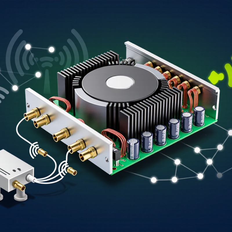
What an RF Power Amplifier Is
A radio-frequency (RF) power amplifier is an electronic circuit that raises the power of a high-frequency signal before it reaches a load, such as an antenna or test instrument. It does not create the original information. It strengthens a signal already shaped by an oscillator, modulator, or earlier circuit. Think of a small waveform entering the amplifier and leaving with greater voltage or current at a frequency suited to radio transmission. Not louder in the ordinary audio sense.
Inside, active devices such as transistors draw energy from a DC supply and use the input signal to control a larger output. Matching networks at the input and output help transfer energy between the circuit and its source or load. A heat sink may sit beneath the device; even a compact amplifier can become warm during sustained operation. Gain describes how much signal power increases, while linearity indicates how faithfully the output follows the input. Efficiency matters, too, because unused power often becomes heat. These goals compete. That balance is rarely perfect, and a design that works well at one frequency or output level may perform less cleanly elsewhere. Careful measurement matters.
Where an RF Power Amplifier Fits in a Radio System
In a typical radio transmitter, the RF power amplifier sits near the end of the signal chain. A modulator creates the information-bearing signal, and frequency-conversion stages move it to the required radio frequency. The amplifier then raises its power before the signal passes through filtering and matching circuits to the antenna. It does not create the message. It makes the radio-frequency signal strong enough to travel farther.
That placement matters. A small transmitter signal may be clean, but the amplifier can add distortion if pushed too hard. For a voice or data link, that distortion may spread energy beyond the intended channel. Engineers balance output power, efficiency, and signal quality, then check the result with measurements rather than relying on a block diagram alone. Heat is real. At higher power, the device needs a suitable thermal path, often through a metal chassis or heat sink.
The antenna and its feed line also affect amplifier behavior. An impedance mismatch can reflect some energy toward the amplifier, reducing performance and potentially stressing components. Filters help control unwanted signals, while careful circuit layout limits losses and instability. In practice, the “last stage” is not always a single component; filters, switches, and matching networks may sit around it. The exact arrangement depends on the radio’s frequency, bandwidth, and operating conditions, so a tidy diagram can hide important trade-offs.
Where an RF Power Amplifier Fits in a Radio System
A representative transmitter signal path, showing how RF power increases before the signal reaches the antenna.
The exciter generates a modulated RF signal, and a driver amplifier raises its level to feed the RF power amplifier (PA). The PA supplies most of the transmitter’s output power; a small amount may be lost in filtering and connections before the antenna. Values are illustrative: 0 dBm = 1 mW, 20 dBm = 100 mW, and 40 dBm = 10 W.
How an RF Power Amplifier Turns DC Power into RF Output
An RF power amplifier increases the strength of a radio-frequency signal by drawing energy from a DC power supply. It does not create useful RF output from DC alone. A small input signal guides how the transistor uses that supply energy. The transistor’s bias voltage sets its operating point, while the changing input waveform controls its current. In effect, the circuit adds power to the waveform without changing its intended frequency. That is the core idea.
The output network then helps deliver energy to the connected load. Matching components—often coils and capacitors—reduce reflections between the transistor and the antenna or test load. Filters can limit unwanted harmonics produced during amplification. A simple diagram makes this process look tidy; real circuits are less forgiving. Component layout, temperature, and the load can all affect performance. For example, a poorly matched load may reduce delivered power and increase heat. Efficiency matters. Not all DC energy becomes RF energy; some becomes heat, which must be managed through board design and cooling. Measurements can also shift slightly with test setup, so repeatable conditions matter. During testing, engineers check output power, distortion, and temperature together, rather than trusting one number.
How Amplifier Classes Differ in Operation and Efficiency
An RF power amplifier raises a radio-frequency signal before it reaches an antenna. Its operating class describes how the output devices conduct during each signal cycle. That choice affects efficiency, heat, distortion, and circuit complexity. Class A conducts throughout the entire cycle, which can produce a clean output. It also wastes considerable power as heat, even when the signal is small.
Class B devices conduct for roughly half a cycle each, improving efficiency but potentially adding distortion where the waveform segments meet. Class AB conducts for more than half a cycle, balancing linearity and power use; many practical designs use this compromise. Class C conducts for less than half a cycle and can be efficient with tuned circuits, but it suits signals that tolerate substantial distortion. Switching classes, such as D and E, use devices more like on-off switches. Their efficiency can be high, though layout, filtering, and load matching matter greatly. The textbook ranking is useful, but real results depend on frequency and operating conditions.
Tips: Check heat and output quality at the intended frequency and load, not just on paper. A tiny mismatch can change performance. Don’t assume the most efficient class is automatically the best choice; signal quality and thermal limits still matter.
Key Performance Measures and Common Applications of RF Power Amplifiers
An RF power amplifier raises a radio-frequency signal before transmission. Its performance is not captured by output power alone. Engineers also measure gain, power-added efficiency (PAE), linearity, bandwidth, and thermal behavior. Gain shows how much the amplifier boosts a signal; PAE compares useful RF output with the DC power consumed. Higher efficiency means less energy becomes heat. That matters in a compact handset, where a tiny enclosure can warm quickly. Linearity matters too: compression and distortion can degrade modulation quality and cause adjacent-channel leakage. A high-power reading can look impressive. It may still be misleading.
These measures shape real applications. Handsets need efficient amplification across changing bands and signal levels, while cellular base stations prioritize linearity and sustained output. Wi-Fi equipment, satellite communications, and radar systems also rely on RF power amplifiers, though each balances bandwidth, power, and heat differently. Ericsson’s June 2024 Mobility Report forecast 5.6 billion 5G subscriptions by the end of 2029, or about 60% of mobile subscriptions. That forecast signals growing demand for radio hardware, but not a single ideal amplifier design. Trade-offs remain. In practice, engineers often test performance under realistic temperatures and signal patterns; a datasheet alone rarely tells the whole story. I would also question peak efficiency figures unless the tested output level and operating conditions are clearly stated.